Monday, October 31, 2005

Screw-up #2

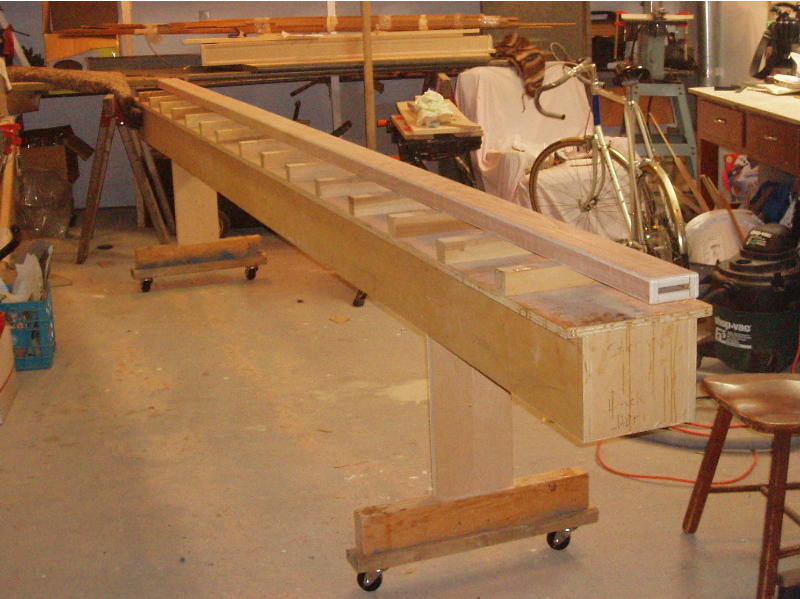
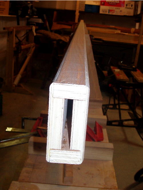
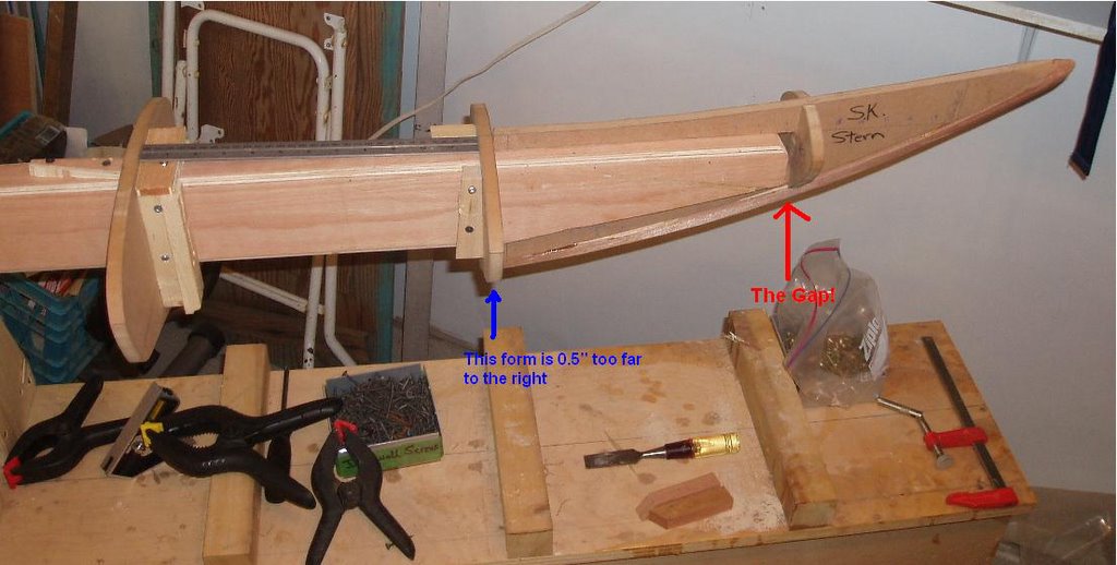
This is my second screw-up so far for those that are counting (well, the second of note anyway). If you look closely at the picture of the stern end form (click on it for a larger version) you might notice that there is a gap of 1/2" between the end of the strongback and the end of slot into which the strongback fits. "Hmmm ... that doesn't look quite right." Last night I realised that I had placed the last form forward of the end form on the aft side of the reference line when it should have been to the forward side of the line. The form is 1/2" thick and therefore, that shifts the end form back by 1/2". See the ruler sitting there - it is 12" and should not fit between the forms, but should be 1/2" too long to fit between. The forms are positioned such that the strips contact the aft edge of the form and thus, it is the aft edge of this form that should have been at the line rather than the forward edge. Oh well, it's easily fixed. Just moving that one form forward 0.5" would have been the simple answer, but it would have meant moving my very carefully aligned form. Instead I chose a different, yet still simple, approach. I tapered the form so that strips would still make contact with the edge of the form that is in the correct position (now the forward edge) and be able to come together at the stern. I then cut 1/2" off of the front edge of the stern end form so that it fit properly where it was supposed to be. The gap disappeared, order was restored to the world. Phwew, good thing I caught that one - who knows what sort of apocalyptic effects it might have had to produce a boat 12.7 mm too long!

[Screw-up #1 occurred a week or two ago while cutting the taper into the boxbeam that holds the forms. The beam must be tapered so that it fits into the narrow ends of the kayak. I cut the one for the bow which went well enough, then I flipped the beam around and thought to myself "better make sure to cut the taper on the correct side because that would be a pretty stupid mistake if I cut them on opposite sides of the beam." And, of course, that's what I promptly did. I realised it before finishing the cut and since the saw has an 1/8" kerf, I filled the gap by gluing in some 1/8" hardboard I had handy. Then I went to bed. After a good sleep and a with a clearer mind, I re-cut the taper properly. You can just barely see the fixed cut in the photo above, but it extends almost all the way through the strongback beam stopping within about 3/4" of the edge.]

Laser Light Show

I borrowed a friend's laser level (thanks Rod!) and used it to project a straight line onto the side of the strongback giving me a reference line in which I had some confidence. I was correct in my suspicion that the line put onto the side of the internal strongback with a string was less than perfect. The aligning of forms has since gone fairly smoothly and with a minimum of frustration. I took my time to get them right so hopefully it's all good. I then installed the endforms which are installed parallel to the strongback and project into the ends of the kayak. The forms are all now fixed in place and a stringline down the center confirmed that they are aligned well in at least that one direction. With everything fixed in place, I flipped the whole thing over so that the hull side (bottom) is up. The hull is the first to be stripped so it is now in position to start the stripping (i.e. attaching strips of cedar to the forms), after I re-check that the forms are all still aligned on the horizontal plane post-flip.

Some of this work was done late Saturday night while listening to the soundtrack of the "Rocky Horror Picture Show" as played in full on the air by CFCR radio (with commentary). Throughout the whole show I kept picturing the play as performed by Shortstuff Productions, and particularly was disturbed by images of Mike (a friend of mine, second from the left in the picture) in his skivvies!

Tuesday, October 25, 2005

More on form alignment

This article describes the various ways my forms are out of alignment. One of my problems is that although I marked a centerline on the strongback, the blocks of wood (cleats) used to hold the forms in place obscure the line. This is a problem since I used cleats on both sides of the form (thanks to the recomendation of Patrick C on the KBBB) to pinch the form in place, but didn't mark the centerline on the cleats (not sure how I could have since the cleats are put in place with the forms in position and thus the forms are in the way of effectively marking the line on the cleats - a catch 22). Also, my "elevation line" marking a horizontal straight line down the side of the strongback may not be 100% due to the fact that when I marked it using a string, the supports that hold the strongback were in the way of having the string run directly against the strongback. I used my combination square to press the string in against the strongback to mark the line, but who knows, it could be out by 1/16" of an inch in places.

Last night I was aligning forms and set up a stringline above the strongback and forms by tying some fishing line to the ends of a pair speed clamps clamped to the ends of the strongback, ensuring that the string was in line with the center-line marked on the strongback. The method I eventually settled on is to clamp a straightedge to the forms so that it is in line with the center-line marked on the form and that in essence extends that center line upwards so that it meets with the string line. I clamped a small level to the form such that it was paralell with one of the horizontal alingment lines on the form (waterline or sheerline). I then nudged the forms this way and that until 1) the ruler marking the center line just touched the string line, 2) the level was level, and 3) the mark indicating the center of the form hole was aligned with the "elevation line" (horizontal line marked on the side of the strongback). For some reason this is proving to be very difficult to achieve as when I nudge the form to get it to line up in one dimension, it shifts out of alignment in the other direction. Then, just when I had it perfect in 3 dimensions, I'd realise that somewhere along the way my ruler or level had shifted out of alignment.

Aaargh.

Distractions

Here is the reason things are not going to progress at lightning speed:


Our second daughter was born on September 23, 2005.

Aligning Forms

What a PITA!

2 down, lots to go.

Sunday, October 23, 2005

Forms

Here's a panoramic view of the forms temporarily set up on the strongback. It looks like I need to stand a little farther back for that function on our camera to work well. I also just noticed that the software stitched the pics together wrong so that there's an extra form in there.
Maybe I'll just stick with opening up the garage door and standing back a few feet.

My first wound of the project. I planed a good chunk out of the tip of my finger. I was holding the piece of wood that will be the internal stem (scrap door-frame mahogany picked up today at Habitat Re-Store) and with my left hand and holding the plane with my right. What I didn't realise was that my finger-tip wrapped around the piece of wood and was in line with the material I was removing.


My next step is to attach all of those forms in a precisely lined up and secure position. So far I've figured out that it's much trickier than it seems. I am finding it difficult for some reason to get the cleats attached to the strongback so that they are square. I guess I'll have to clamp as I screw them down rather than trying to hold them by hand as I had been doing. I've found a couple of points in Nick Schade's book where things weren't quite as clear as I would have liked. I may have to pull all the forms off again and add an "elevation line" in order to line them up with the straight line that's on the side of the strongback. I'll figure it out tomorrow.

Monday, October 17, 2005

I was having a heckuva time trying to add photos to the entry below so I figured I'd sort out the bugs in a separate post. I see the images now so hopefully it's working. I had a separate photo editor open earlier so maybe that was interfering with the upload?

So what you have in these two photos is the 16' long 2x4 that is actually 1 15/16" x 3 15/16". The slightly reduced size is so that the forms fit easily over the beam. The boxbeam or internal strongback is resting on the external strongback. See the earlier post for details.

See that bundle of dark brown strips of wood in the back - that's 95% of the cedar for this boat, and they tell me there's probably 30% extra as a fudge factor. I also have some contrasting light coloured strips thanks to Rod Tait but they are much longer and on the shelf out of these photos. I'll have to post some better photos of the strips some time later.

Two Strongbacks Better than One?

Canoes are typically built on an external strongback - essentially a rigid beam on which the forms are mounted above the strongback. Kayaks may use an external or internal strongback. An internal strongback is a beam where the forms for the boat are placed around the beam such that the beam pierces the form and the boat is built around the beam and form structure. A few years ago I purchased an external strongback along with the forms for a Kipawa canoe. I have never quite gotten around to building the canoe but since I had the strongback I thought that I might as well put it into service as a very rigid platform to support the internal strongback for my kayak, much as Dale did (in fact it was seeing his web site that gave me the idea and convinced me to ditch the sawhorses). An internal strongback is usually supported on a pair of sawhorses.

I find it interesting that there is such a difference in opinion out there. The canoe-building folks and followers of Ted Moores in particular, seem to believe that the strongback has to be incredibly rigid and even epoxy the strongback to the floor to prevent it from ever shifting, even though a strongback built to the Moore's design is an incredibly solid piece of wood. The kayak-building folks, and followers of Nick Schade in particular, opt instead for using a crooked 2x4 supported on a couple of rickety sawhorses as their backbone for building. I guess I chose to combine the methods. Rather than use a 16' 2x4 (ever see a straight one?), I chose to make a 2"x4" box beam strongback out of 3/4" plywood. The resulting beam is not as rigid as I might have expected, but at least when it's done wobbling it returns to a straight line. Although I had made a pair of sawhorses, I am instead mounting the internal strongback on supports mounted on the Moores'-style external strongback. Since this provides me a nice rigid platform to build on, I have mounted the whole apparatus on 4 casters so that I can move it around in my space-limited shop. Sure, it might flex a couple of thousandths of an inch as I move it around, but it should still be better than the sawhorses.

For an interesting and evolving perspective on a boxbeam-type internal strongback, see Bryan Hansel's comments during the building of a kayak of his own design. He started off hating the internal strongback, but by the end he seemed to like it.

Preparations

I have spent the last week preparing to build our kayak by building an internal box-beam to hold the forms and setting up the strongback to hold the box-beam. The box-beam is a 2"x4" beam constructed of 3/4" plywood with the corners rounded using a router. The idea is to create a dimensional stable (so it won't warp) and straight platform on which to build the kayak. The forms have a 2"x4" hole through the center so that they are fastened along the length of the beam with a spacing of 12". The result when it is set up should be a sort of kayak skeleton upon which the strips of cedar are attached to form the boat.